![]()
sales@1machinery.com
|
|
+1-819-346-2369 sales@1machinery.com |
Specifications
| Ask for quotation | |
| Stock ref. # 1612 |
|
|
Other specifications
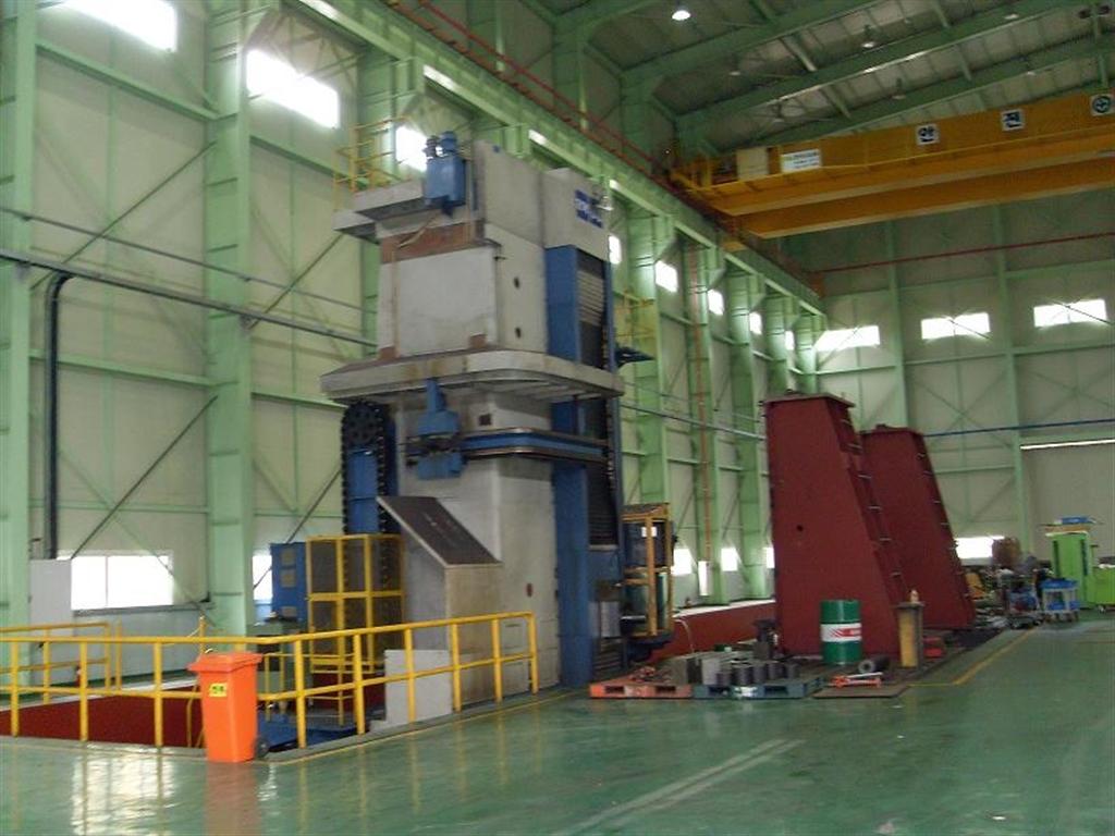
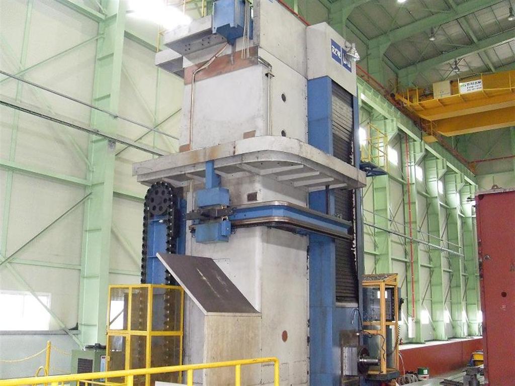
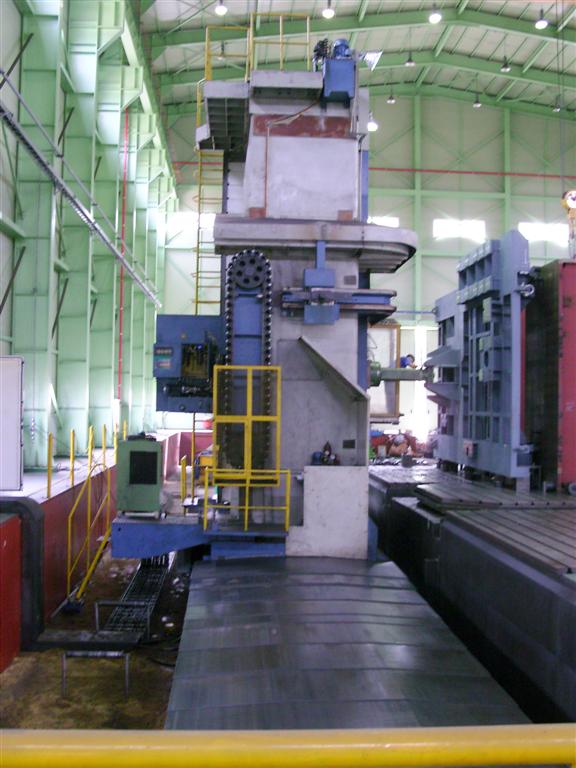
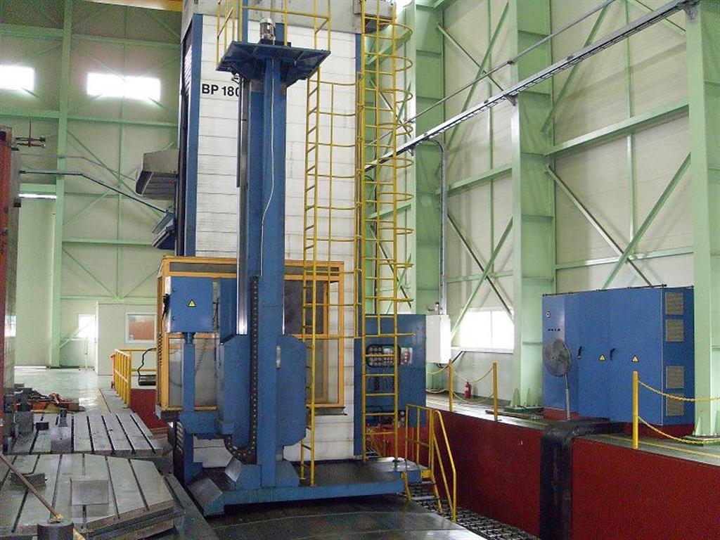
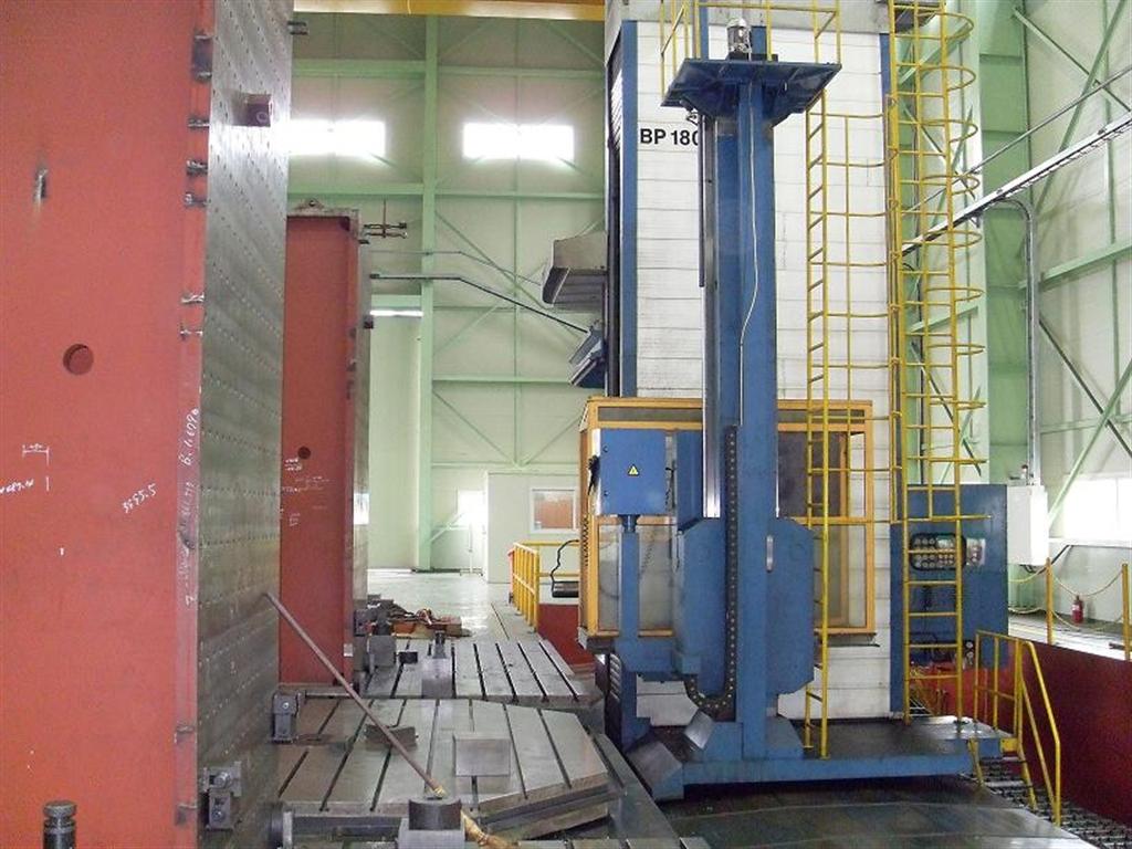
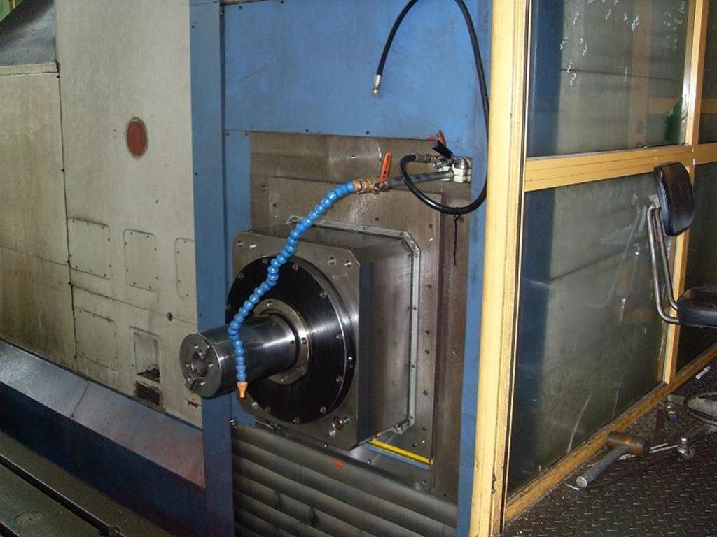
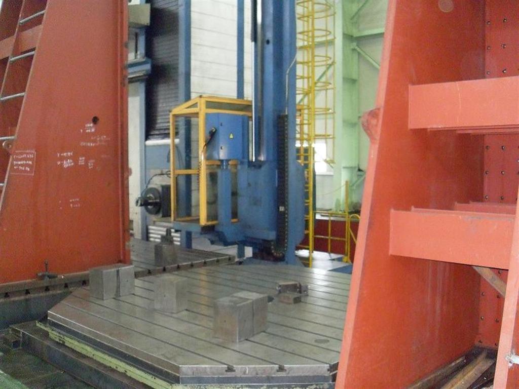
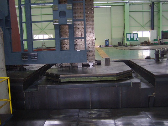
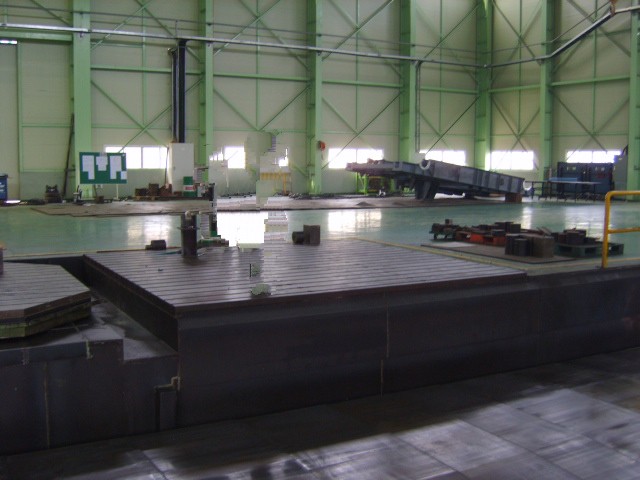
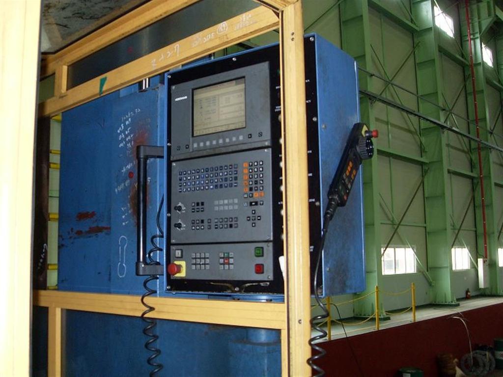
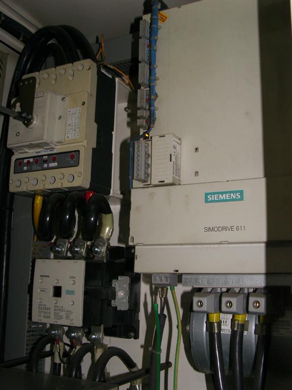
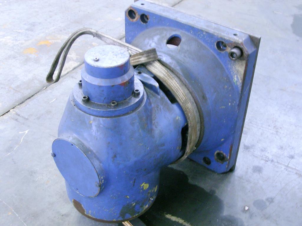
7.08" WMW AFP 180 CNC FLOOR TYPE HORIZONTAL BORING MILL, 2002 YEAR: 2002 MODEL: AFP 180 CNC CONTROL HEIDENHAIN TNC 430. (8-AXIS CNC) SPINDLE DIAMETER 180 MM SPINDLE TAPER ISO 50 SPINDLE SPEED RANGES (2 STEP) 5 ~ 2,500RPM MAIN MOTOR POWER 60 KW X-AXIS TRAVEL (COLUMN) 14,200 MM Y-AXIS TRAVEL (HEADSTOCK) 4,500 MM Z-AXIS TRAVEL (SPINDLE) 1,200 MM W-AXIS TRAVEL (RAM) 900 MM AUTOMATIC TOOL CHANGER 60 100 TON CNC ROTARY TABLE MAX. LOAD CAPACITY 100 TON - TABLE SIZE ------------------------------------- 3,500 X 3,500 MM - TABLE ROTATION SPEED --------------------------- 1.0 REV/MIN - INDEXING POSITION, INCREMENTS ------------------ 360.000 DEGREE * FEEDS RATES. - WORKING FEED RATES (X,Y,W) --------------------- 5 ~ 3,500 MM/MIN - RAPID FEED (X,Y AND W) ------------------------- 10 & 12 M/MIN - Z-AXIS ----------------------------------------- 6,000 MM/MIN - Machine Bed. The bed has heavily ribbed cast iron construction, with guide ways of hardened and ground steel pate inserts. - The Column Saddle. The column saddle is made of cast iron and moves along the bed guide ways (X-axis) Saddle guiding is achieved by hydrostatic guide ways. - Column. The double wall, ribbed cast iron column supports the headstock that travels along the two vertical guide ways of the column (Y-axis) that have hardened and ground steel plate inserts. A counterweight, to balance the headstock is guided inside the column. - Headstock. The headstock is a heavily ribbed cast iron structure designed to withstand the extensive forces generated by the main motor. The headstock houses the spindle assembly and slides along the vertical guide ways of the column. The headstock guide ways are lined with anti-friction material. A Siemens motor through a German made precision ZF gearbox, and drives the spindle. - Spindle Assembly. The sleeve-type spindle assembly is composed of the milling spindle and boring spindle. Its bearing feature high precision angular grease lubricated ball bearings four in the front and two in the rear. Cooling is activated by a closed circuit oil refrigerated system inside the outer spindle sleeve. - The boring spindle is guided inside the milling spindle by nitrated bushings. The ISO 50 taper allows automatic clamping and unclamping by the mechanical- hydraulic system inside the boring spindle. Both its external surface and the ISO 50 taper are nitrated. The rear side bearing consists of four radial-axial ball bearings, mounted within the special cast iron bearing of the ram. This one is actuated by the ball screw nut, which creates the Z-axis feed motion. - Automatic Tool Clamping /Unclamping Mechanism. The tool clamping/unclamping is located inside the boring spindle and the back bearing body. Tool clamping is mechanically performed by disk springs. Tool unclamping is achieved hydraulically. - The hydraulics. Are provided by ATOS according with customer desire. - Feed Mechanisms. The feed movements on X, Y driven by a gearbox W, Z axes are driven via timing belt transmissions with reduction ratio by servo motors with step less variation of the speed, independent on each axis. - Measuring Systems. The X, Y axes have Heidenhain linear scales and the B, W, Z-axes have Heidenhain rotary encoders. - The Tools magazine. Have 60 positions and are driven by AC Siemens motor with reducer. The high precision are assured By a rotary encoders made by Heidenhain. - Main Features. Linear HEIDENHAIN scales for X, Y axes. Rotary HEIDENHAIN encoder for B, Z, W axis and spindle orientation. Infinitely variable SIEMENS AC servo drives (X, Y, Z, B, W) Ball screws on all linear axes (Y, Z, W) 2-Step spindle drive gear box, made ZF (Germany), is electrically shifted. Nitrated boring spindle. High precision bearings for the milling spindle. Hardened and ground ways for X, Y(steel inserts) Counter ways lined with anti- friction material. Double wall column. 4 Clamping cylinders for rotary table. Thread cutting through CNC program. Mechanical power tool clamping, hydraulic unclamping. Safety limit switches on all axes. Coolant through spindle equipment (optional) Centralized operator control station. - Hardware Configuration. LE 430 logic unit. TE 420 keyboard unit. BF 120 color flat panel. PL 410 extension card for the PLC 2 pcs. Machining operating panel MB 420. HR 410 electronic hand wheel - Capabilities. The HEIDENHAIN TNC 430 in the configuration presented enables contouring control of 8 axes (X, Y, Z, W, B, W1 and tools magazine) plus Oriented Spindle Stop Control. - Configuration Performance Capability. 3D linear interpolation, 5 axes. 2D circular interpolation, 2 axes of 8 linear ones. Helical interpolation (combination) Rigid tapping. - Scales and Encoders. The machine main linear axes (X, Y, W1) are provided with incremental HEIDENHAIN linear scales, LB type, while spindle revs, table rotary movement and W, Z axes are picked up by the HEIDENHAIN ROD rotary encoders. - Programming Features. 0.1 degree increment for programming in the 4 linear axes (X, Y, Z, W, W1) 0.001 degree increment for programming in the B rotary axis. 0.1 degree increment for programming in the C rotary axis {the spindle rotation} Metric/inch conversion. Analog programming of spindle speed direct in rpm. Canned cycles: pecking, slot milling, pocket milling and tapping. Program data Input: HEIDENHAIN conversation or ISO code format, data output in ISO code. User program memory capacity; 12,000 blocks, 64 user programs maximum. Universal RS 232-C/v.24 and RS 422/v.11 interface. Capable of the following operation modes: a) Automatic mode. b) Jog (set Up mode) c) TEACH In mode. d) MDA mode (manual data Input)
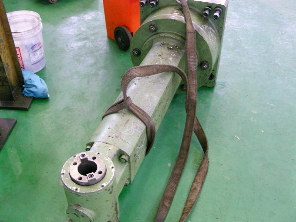
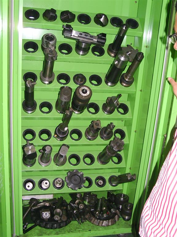
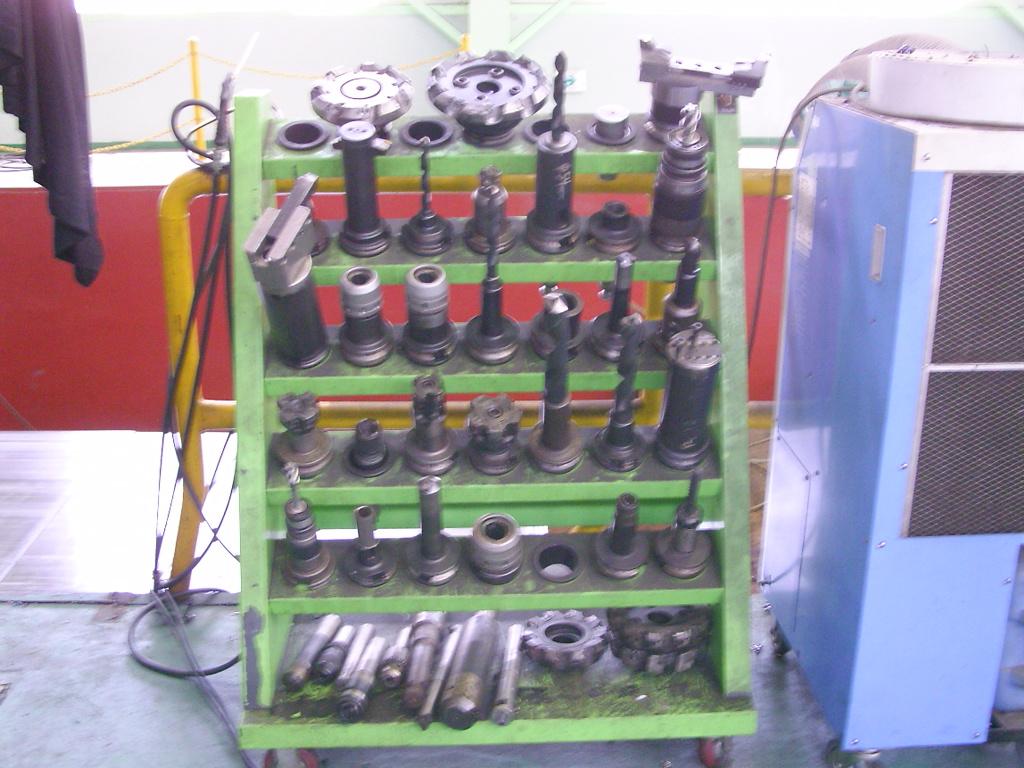
Photos
|
Machinery
Inc. |