![]()
sales@1machinery.com
|
|
+1-819-346-2369 sales@1machinery.com |
Specifications
| Ask for quotation | |
| Stock ref. # 0956 |
|
|
Other specifications
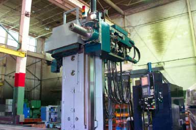
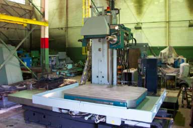
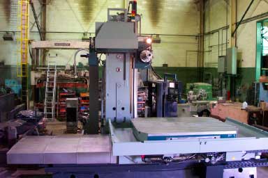
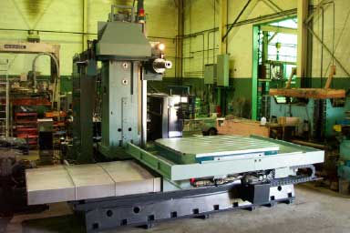
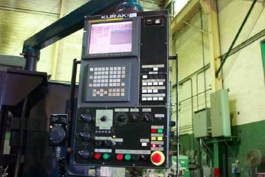
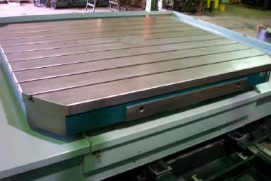
KURAKI High Speed type CNC Horizontal Boring & Milling Machine * * * 8000 RPM – Workload on Table 33,000 Pounds * * * KBT-15BHA with Fanuc 16i-MA Control Installed: 2000 Main specifications Stroke X axis travel (Table longitudinal) . . . . . . . . . . . . . . . . . . . . 118.11" Y axis travel (Spindle vertical) . . . . . . . . . . . . . . . . . . . . . 90.55" Z axis travel (Column cross) . . . . . . . . . . . . . . . . . . . . . . . 62.99" W axis travel (Spindle axial) . . . . . . . . . . . . . . . . . . . . . . . 15.75” Table top ~ spindle center . . . . . . . . . . . . . . . . . . . . . . . . . 0 ~ 90.55" Table center ~ spindle nose / W=0" . . . . . . . . . . . . . . . . . 35.43 ~ 98.43" Table center ~ spindle nose / W=1572" . . . . . . . . . . . . . . 19.68 ~ 82.67" Table Table size . . . . . . . . . . . . . . . . . . . . . . . . . . . . . . . . . . . . . 78.74" x 98.42" Table maximum loading capacity . . . . . . . . . . . . . . . . . . 33,000 lbs Table top profile . . . . . . . . . . . . . . . . . . . . . . . . . . . . . . . 0.87" x 7 pc's T slot Table auto indexing . . . . . . . . . . . . . . . . . . . . . . . . . . . . 0.001 degree / full B axis Spindle Head Spindle (Quill) diameter . . . . . . . . . . . . . . . . . . . . . . . . . 7.87” Spindle speed (for every 1 rpm) . . . . . . . . . . . . . . . . . . . 50 ~ 8000 rpm Spindle speed change range . . . . . . . . . . . . . . . . . . . . . . 2 steps (double winding) Spindle taper . . . . . . . . . . . . . . . . . . . . . . . . . . . . . . . . . . 7/24 taper No 50 Feed Rapid traverse . . . . . . . . . . . . . . . . . . . . . . . . . . . . . . . . . 393.70 in/min - X, Y, Z axis 236.22 in/min - W axis Feed rate . . . . . . . . . . . . . . . . . . . . . . . . . . . . . . . . . 0.04~314.96 in/min - X, Y, Z axis 0.04 ~ 236.22 in/min - W axis Table (B axis) revolution . . . . . . . . . . . . . . . . . . . . . . . . . 1.0 rpm ATC Tool shank . . . . . . . . . . . . . . . . . . . . . . . . . . . . . . . . . . . . BT 50 Pull stud . . . . . . . . . . . . . . . . . . . . . . . . . . . . . . . . . . . . . . MAS P50T-1 (45 deg) Tool storage capacity . . . . . . . . . . . . . . . . . . . . . . . . . . . . 60 pc’s Max tool diameter . . . . . . . . . . . . . . . . . . . . . . . . . . . . . . 4.92” - full pots 9.45" - vacant adjacent pots Max tool length . . . . . . . . . . . . . . . . . . . . . . . . . . . . . . . . 15.75” Max tool weight . . . . . . . . . . . . . . . . . . . . . . . . . . . . . . . . 55 lbs Tool selection . . . . . . . . . . . . . . . . . . . . . . . . . . . . . . . . . At random Motor Spindle motor . . . . . . . . . . . . . . . . . . . . . . . . . . . . . . . . . AC 40 / 35 HP (30min/cont) Feed motor. . . . . . . . . . . . . . . . . . . . . . . . . . . . . . . . . . . AC 9.9 HP - X axis AC 8.2 HP - Y, Z axis AC 5.2 HP - W axis AC 8.2 HP - B axis Voltage 200/220-60-3 Power capacity . . . . . . . . . . . . . . . . . . . . . . . . . . . . . . . . 85 kVA Air pressure source . . . . . . . . . . . . . . . . . . . . . . . . . . . . . 0.5 MPa 1000 NL/min (atm) Dimensions Machine height . . . . . . . . . . . . . . . . . . . . . . . . . . . . . . . . 212.59" Floor space . . . . . . . . . . . . . . . . . . . . . . . . . . . . . . . . . 314.96 x 309.05" Machine weight . . . . . . . . . . . . . . . . . . . . . . . . . . . . . . . . 93,500 lbs EQUIPPED WITH: Coil type chip conveyors Spindle cooling device Manual pulse generator Work light & signal light Power shut off device Mono lever type jog feed Scale feedback system (X, Y, Z, W and B axis) Self-diagnosis function Door interlock for EC cabinet Coolant thru spindle – Flange thru type – 150 PSI Extra large capacity coolant device with lift up chip conveyor. Extra large capacity lubrication tank Splash guard type B Column Guards Actual spindle speed display on LCD Helical interpolation Tool offset 64 pairs Tool offset memory C Rigid tapping Part program storage length 1280 m Tool length measurement Remote buffer interface Interruption of magazine rotation High precision contour machining function (HPCC) Custom macro function with 600 variables Macro pattern cycle Coordinate system rotation Auto corner override Optional chamfering/corner R Programmable mirror image Sub control panel Manual handle interruption External air blow Fanuc 16i_MA standard specifications [Control axis] Control axis 5 axes (X,Y,Z,W,B axis) Simultaneously controlled axis 4 axis : Positioning G00 Linear interpolation G01 2 axis : Circular interpolation G02/G03 Control axes expansion [Program input] Least input increment 0.0001" (X,Y,Z,W axis), 0.001 deg (B axis) Max programmable dimension +/- 8 digits Absolute / increment programming (combined use in same block) Tape code EIA/ISO auto recognition Decimal point programming / pocket calculator type decimal point programming Inch / metric change [Interpolation function] Positioning (Linear interpolation type positioning is possible) Linear interpolation Multi-quadrant circular interpolation Tangential speed constant control Helical interpolation Bell-shaped acc / dec after cutting feed interpolation Feed rate clamp based on arc radius [Feed functions] Feed per minute Rapid traverse Dwell Rapid traverse override (F0, 25, 50, 100%) Feedrate override 0 ~ 240% (every 10%) Exact stop, Exact stop mode, Cutting mode, Tapping mode, Manual handle feed 1 unit [Program storage & editing] Part program storage length 1280 m Number of registerable program 400 Part program editing Background editing Program name 16 characters Program number 4 digit Program number search Sequence number N5 digit Sequence number search Main program / sub program [Operation display] LCD / MDI panel 104” color LCD Clock function Run hour and parts count display Load meter display Alarm message display Alarm history display Operation history display Periodic maintenance screen Maintenance information screen Actual spindle speed display on LCD [Data input / output functions] Erase CRT screen display Reader / puncher interface 1 Modem card control Memory card interface (for ATA flash memory card, 3V) Data server function for ATA flash card Screen hard copy [S M T functions] S function T function M function [Tool compensation] Tool length compensation Cutter compensation C Tool offset 64 pairs Tool offset memory C Tool length measurement [Coordinate system] Reference point return manual / auto (G27, G28, G29) 2nd reference point return Machine co-ordinate system selection (G53) Work piece co-ordinate system selection (G54 ~ G59) Work piece co-ordinate system setting (G92) Work piece co-ordinate system preset (G921) Local co-ordinate system setting (G52) [Operation help functions] Program stop Optional stop Single block Optional block skip 1 pc Dry run All axes machine lock Z, W axis command cancel Auxiliary function lock Mirror image (setting and M command) Manual intervention and return Directory display and punch for each group Help function Program restart Restart of block [Program help functions] Circular interpolation by R programming Canned cycle (G73, G74, G76, G80 ~ G89, G98, G99) Rigid tapping [Precision compensation] Stored pitch error compensation Backlash compensation for each rapid traverse and cutting feed Single direction positioning [Maintenance & Safety] Over travel Stored stroke check 1 Self-diagnosis function Maintenance screen [Machine help functions] Buffer register
Photos
|
Machinery
Inc. |